Basic Controls
The Probe
First, keep the switch on the probe set to Select
Connecting Rows
Click the Connect button on the probe
The logo should turn blue and the LEDs on the probe should also change
Now any pair of nodes you tap should get connected as you make them. In connect mode, you're creating bridges (see the glossary), so connections are made in pairs. When you've tapped the first node in a pair, the logo and Connect text on the probe will brighten to show that you're "holding" a connection, and the next thing you tap will connect to that first node.
If you make a mistake while holding a connection, click the Connect button and it will clear it and take you back to the first node.
If you click the Connect button while you're not holding a node, it will leave probe mode and bring you back into idle mode (rainbowylogo, all 3 probe LEDs on.)
To get out of Connect mode, press the button again.
If you make a connection you didn't mean to, double-tap Remove to undo it - see Undo / Redo.
Encoder Connections
You can also make connections using just the clickwheel, without needing to touch the probe to the breadboard:
To activate:
- Navigate to: Click > Connect > Add (or Remove)
- OR just turn the clickwheel while already in probe mode
How it works: 1. Turn the clickwheel to scroll through all available nodes: - Breadboard rows (1-60) - Nano header pins (D0-A7) - Rails (Top, Bottom, GND) - DAC (0, 1) - ADC (0-4, Probe) - GPIO (1-8) - UART (TX, RX) - Current sense (I+, I-)
- Click the encoder button to select the highlighted node
- Hold the encoder button to exit
The cursor will automatically hide after 5 seconds of inactivity. This is especially useful when you need precise control or want to access special functions without tapping pads.
Removing Rows
Click the Remove button
and the logo should turn reddish
Now you can swipe along the pads or tap them one at a time. Remember it only disconnects that node and anything connected to it directly, not everything on the net. So tapping say, row 25 that's connected to GND won't clear everything connected to GND, but tapping the - on the rails (for GND) would.
The special functions work the same way, tap the pad, pick one, and it will remove it. Click the button again to get out.
If you delete the wrong row, double-tap Remove to undo it (or use the History scrub menu to walk back further) - see Undo / Redo.
Probe Notes
Remember the probe is read by a resistive voltage divider, so putting your fingers on the pads (or the back sides of the 4 risers that connect those probe sense boards to the main board), or anything causing the probe tip not to be at a steady 3.3V will give you weird readings.
If you can't seem to stop playing with the switch on the probe, run the app probe calib and tap around on the board while turning the clickwheel until the place you tapped is always spot on (do this with the switch in both modes), and hold the clickwheel button to save. This adjusts the nominal 3.3V measure mode puts out should be fairly accurate enough for probing.
The Click Wheel
There are two kinds of presses, click (short press) and hold (long press). In general, a click (short) is a yes, and a hold (long) is a no/back/exit/whatever.
When I say click, it's more of a diagonal slide toward the center of the board (these encoders were meant to poke out just a little bit from the side of a tablet or whatever.)
To get to the menu, click the button and scroll through the menus, click will bring you into that menu, hold will take you back one level. If you have trouble reading stuff on the breadboard LEDs, everything is copied to the Serial terminal and the OLED (talked about in OLED Section), and adjusting the brightness may help; in the menus, it's Display Options > Bright > Menu and then scroll around until you find a level you like, then click to confirm.
Special Functions
To connect to special functions, tap the corresponding pad near the logo, it will show you a menu on the breadboard and terminal to choose them.
You can think of special functions just like any other node, the only difference is they're in a sort of "folder" so I didn't need to put a dedicated pad for each of them.
DAC Pad
 └─ 0 1 [Tap pads below selection]¹
  └─ -8V  !:.:!  +8V [Tap bottom pads or use clickwheel to select a voltage] > [click probe Connect button to confirm]²
   └─ [Tap a row to connect it to] (or if you were already "holding" a node, it'll connect there)³
(This is an ASCII version of what will show on the breadboard LEDs)
¹
²
³
GPIO Pad
 └─ ⁱ1⁰ ⁱ2⁰ ⁱ3⁰ ⁱ4⁰
    ₁5₀ ₁6₀ ₁7₀ ₁8₀ [Tap pads to choose which `GPIO` (left side for input, right side for output)]
     └─ [Tap a row to connect it to] (or if you were already "holding" a node, it'll connect there)
¹
The 4 user pads will be remappable in the future, but for now, top_guy is routable UART Tx and bottom_guy is routable UART Rx, and building pads are Current sense + and -.
The building pads have multiple functions:
- In idle mode: Override colors for net highlighting (see Idle Mode Interactions)
- In connect/remove mode: Access Current Sense (I+/I-) with marching ants visualization!
Current Sensing with Marching Ants
When you tap either building pad in connect or remove mode, you'll get access to the current sense inputs (I+ and I-). When both I+ and I- are connected to different nets in your circuit:
- A virtual wire appears between the two nets containing the
I Sensenodes - Animated "marching ants" flow along this wire showing current direction
The animation automatically picks the where to put the virtual "wire". It will search other nodes on the same nets that I sense + and I sense - are on it prefers places where they're on the same level so it can actually draw a connecting wire and not just be vertical lines.
!!! warning I Sense + and I Sense - go on different nets but they're shorted internally
They're two ends of a 2Ω shunt resistor, so remember that these will be shorted together. You measure current in series so this is expected, but it's super easy to forget. Take this warning as the equivalent of your multimeter yelling at you when you have the probes in the current holes and have it set to voltage.
Undo / Redo
Every change you make to your circuit gets recorded into an in-memory history ring, and there are two ways to walk back through it: a fast probe-button gesture for one-step undo/redo, and a full scrub menu on the click wheel for going further.
Double-tap the probe buttons
Double-tap Remove -> Undo (reverts the last change)
Double-tap Connect -> Redo (reapplies a previously undone change)
- The
logoflashes yellow for ~600 ms - The OLED shows a 2-line toast like:
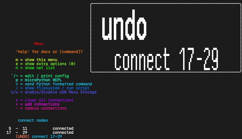
History scrub via the click wheel
If you want to walk back further than one or two steps and see each state on the breadboard as you go:
- Open the menu (short
clickthe wheel) - Find the History entry,
clickin - Now turning the wheel scrubs through every recorded transaction:
- CW = step backward in time (one txn older)
- CCW = step forward (newer / into redo land)
- The breadboard updates in real time as you scrub - actual crosspoints flip and
LEDs change, so you can see exactly what each state looked like - The OLED shows the position (
-3/12) and the txn label (connect 50-46) at each step - Encoder
clickOR probeConnect= commit (cursor stays where you stopped) - Encoder
holdOR probeRemove= cancel (rewinds to where you were when you opened the menu)
Caveats
- History is fresh on every boot - undo doesn't survive a power cycle. This is intentional: nothing about your saved
slotfiles is touched by undo, only the in-session ring of changes you've made since powering on. - The ring holds ~16,000 ops / 4,000 transactions on V5 hardware (PSRAM), or ~512 ops on SRAM-only builds. Older edits roll off as you make new ones - waypoint decimation keeps the recent history dense and the older history sparse, so the ring covers a long timespan without bloating.
Idle Mode Net Highlighting
The main thing is that there's a lot more interaction that can be done outside of any particular mode (like not probing and the logo is rainbowy, I'm gonna call this idle mode here until I think of a good name)
Here's what's new (all of this is in idle mode):
Basic Interactions
- Tapping nets highlights them as before, but there's a slightly different animation on the
rowyou have selected from the wholenet - The click wheel scrolls through highlighting
rowsas if you tapped each one
Row Selection Actions
With a row selected, here's what you can do:
Connect Button
connectbutton will bring you into probing mode with the highlighted row already selected and then spit you back out toidlemode once you've made a connection to another row, or clickconnectagain to exit
Remove Button
removewill remove the highlightednode
Measurement Display
- if the highlighted row is a
measurement(gpio inputoradc) it will print the state to serial and the oled
Output Toggle
- if the highlighted row is an
output(gpio output, I'll eventually dodacstoo) clicking theconnectbutton will toggle ithigh/low. Theremovebutton will just unhighlight the net (there were some choices here, like make each button assigned to high / low or allow removing them, but this felt like the best way after trying them all). I will eventually add a setting for the toggle repeat rate (set to 500ms now) and a way to set it freewheeling as a clock.